Departure
I wanted a private audio channel, not another speaker. The bet was simple enough to test: send Gemini Live through a cheap amplifier, drive a coil of magnet wire, place a tiny neodymium magnet near the ear, and let the changing magnetic field do the rest.
Approach
- LM386
- TPA3118
- Induction coil
- 30 AWG magnet wire
- 26 AWG magnet wire
- Neodymium magnets
- 9V battery
- Gemini Live
$34 gift card balance, parts from one order, and a school-day noise floor that was much less forgiving than a quiet room.
Field log
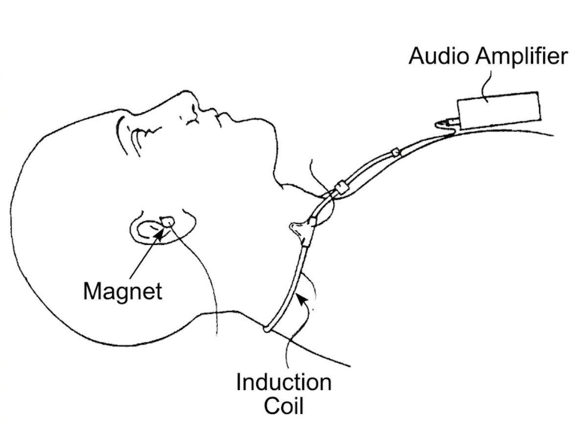
The system had four pieces: audio source, amplifier, coil, magnet. Current through the loop creates an alternating magnetic field. The magnet near the ear moves with that field. If it moves enough, the ear hears sound without a normal speaker.
Audio in, current through the loop, magnet motion at the ear. The first build stayed inside the gift card: LM386 amplifier module, 30 AWG magnet wire, 5x2mm neodymium magnets, a 9V battery lead, a battery, and an aux cable. It was enough to make the experiment real, but not enough to give it much headroom.
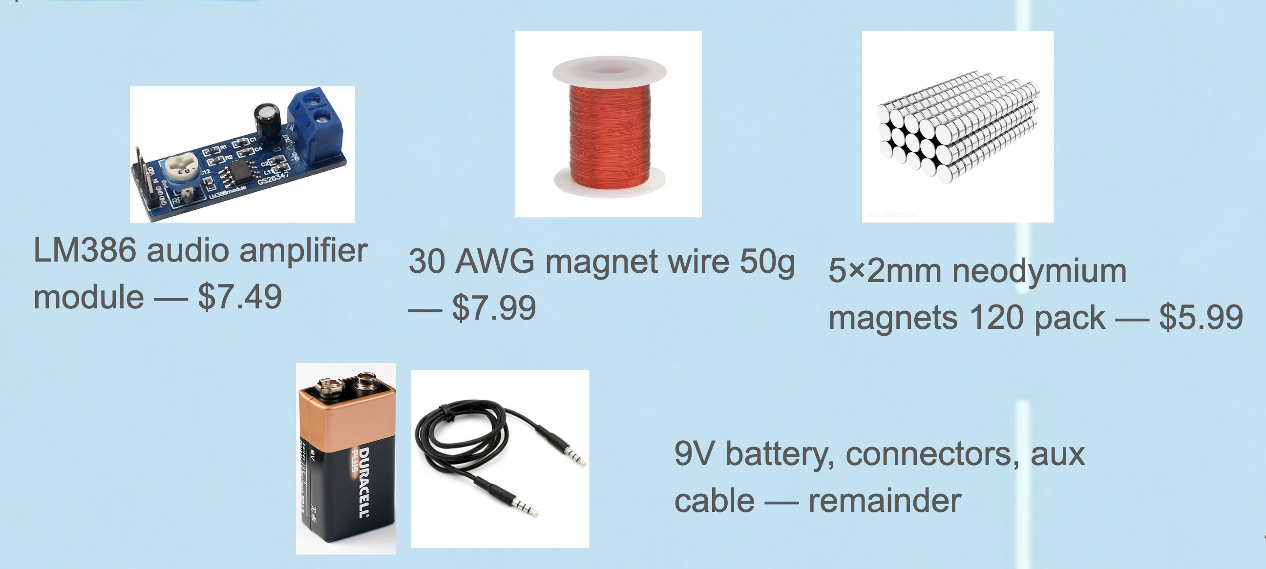
A $34 proof-of-physics order. In a quiet room, the rig crossed the threshold. Laptop audio into the LM386, magnet-wire loop on the desk, tiny magnet by the ear. Gemini Live became faint but real: not loud, not stable, but present.
Most of the first failures were mechanical. Magnet wire enamel resisted solder, aux cable strands frayed, and exposed copper turned every movement into a new short. Before the physics mattered, the joints had to stop lying.
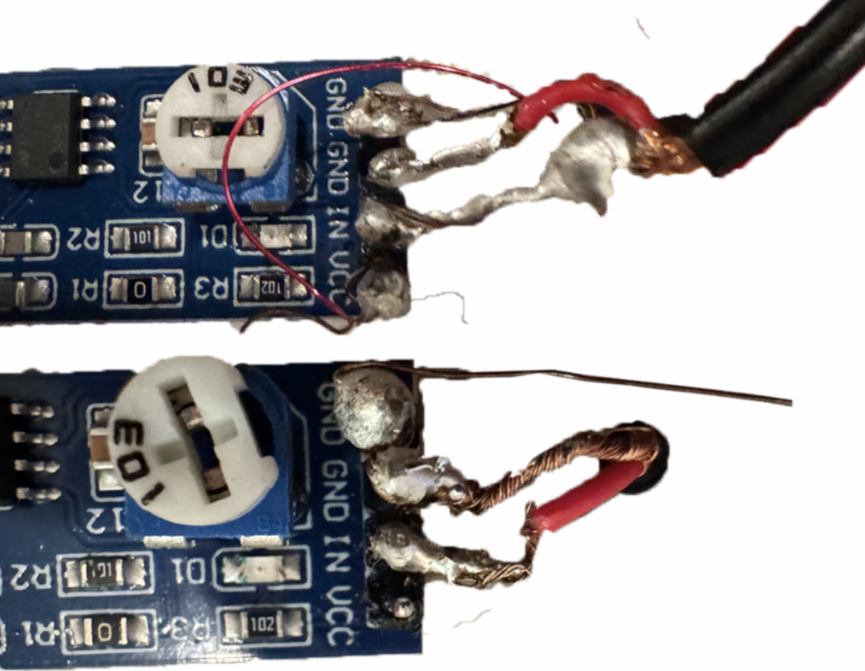
The first real lesson was soldering magnet wire cleanly. The next day, the same rig collapsed in a hallway. It only came back if I cupped both ears and stopped moving. The quiet-room win was real, but the school noise floor was the actual test, and the LM386 did not have enough authority.
My first instinct was more coil turns. The math did not care. More turns increases magnetic field per amp, but it also increases resistance and lowers current from the same supply. In this setup, loudness lived more in amplifier voltage, amplifier power, and wire gauge than in another wrap around the loop.
I tried to brute-force the LM386 with more voltage and hit the ceiling the obvious way. The board class was wrong for the job: too little power, too little supply voltage, and no margin for a noisy room.

The useful failure: the board was the ceiling, not the idea. The comparison made the next direction obvious. The LM386 puts about 0.7W into the loop and handles 15V. A TPA3118 board can run at 24V and output about 30W. Pair that with thicker 26 AWG wire, and the experiment moves from barely audible to at least electrically plausible.
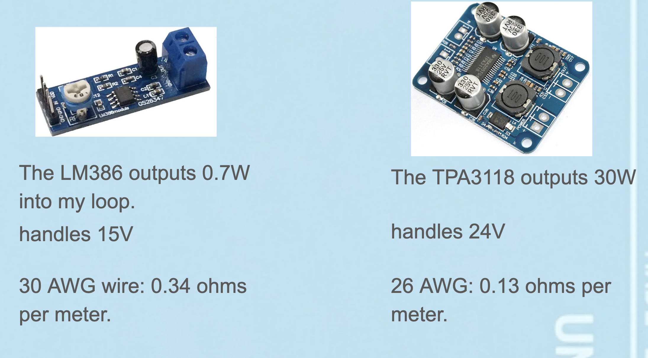
Same concept, different class of amplifier and lower-resistance wire.
From the gallery
What I came back with
Lesson from the terrain
The project failed in the useful way. The induction idea worked just enough to prove the path, then failed loudly enough to show the real constraint. More turns were not the answer; the amplifier and wire resistance were. At this scale, the invisible voice is less about clever geometry and more about giving the magnetic field enough current to survive the room.